Bridge & Infrastructure Scanning
Survey-grade 3D laser scanning for bridges, overcrossings, tunnels, tanks, rail and roadway corridors, plants, and utility structures, tied to a least-squares-adjusted control network so every point carries a known accuracy. Clearance surveys, structural as-builts for retrofit and rehabilitation design, deformation baselines, and pre-construction documentation for agencies, engineers, and contractors across the Bay Area.
Accuracy You Can Put a Stamp On
- Control-network-tied scans with a stated, defensible accuracy
- Vertical and horizontal clearance surveys from the point cloud
- Structural as-builts of decks, soffits, bents, abutments, and bearings
- Deformation baselines and repeat epochs for movement analysis
- Rail, roadway, and utility corridor capture with minimal closures
- Tanks, tunnels, and plant piping documented without contact
- Deliverables in your agency CAD standard, NAD83/CSRC and NAVD88
- Licensed surveyor responsible for control, datum, and certification
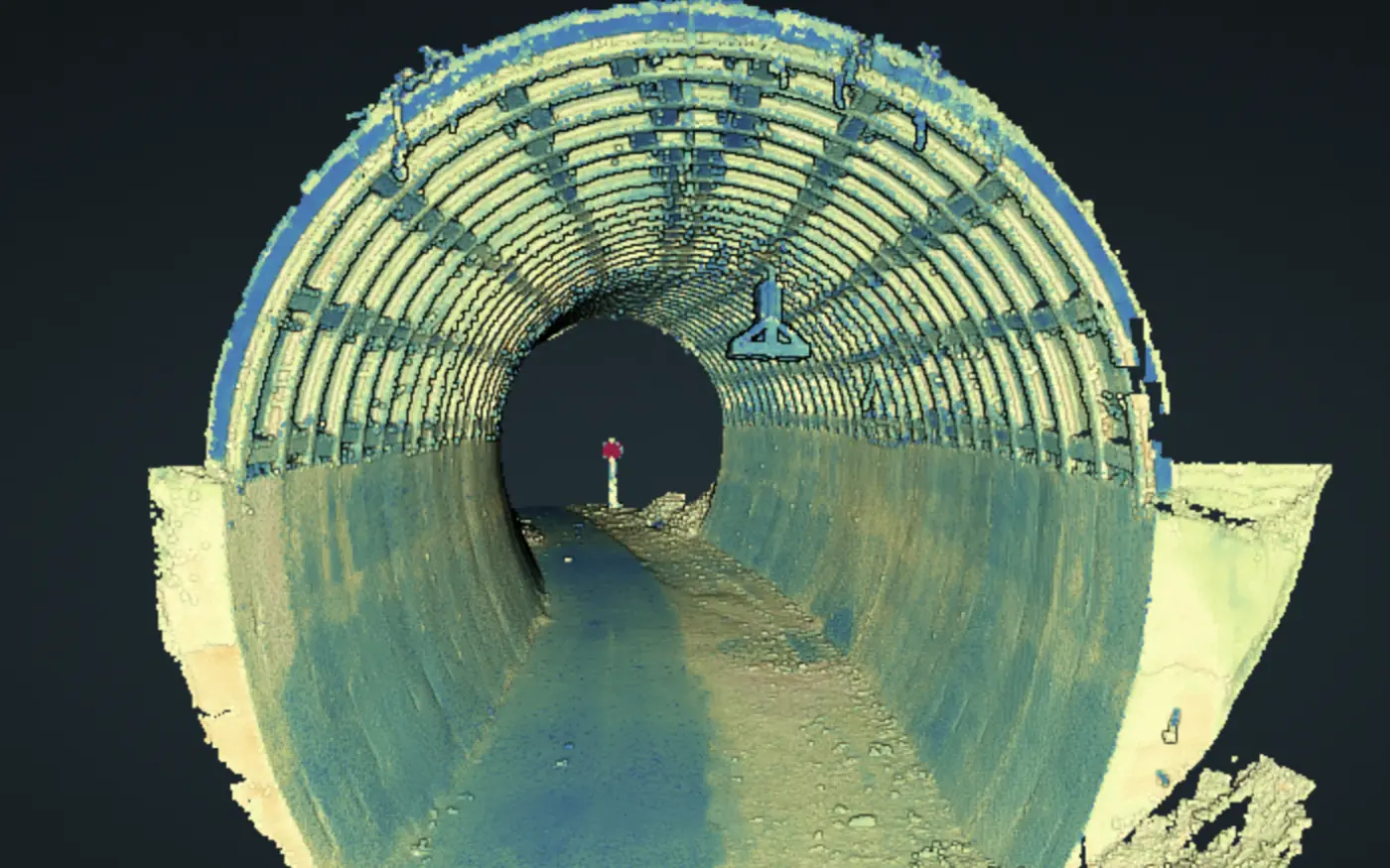
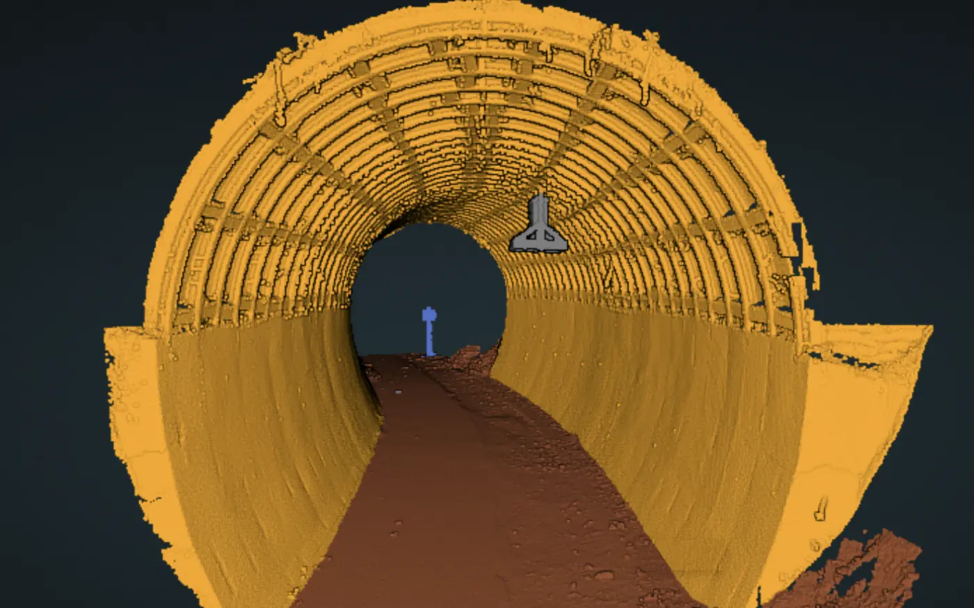
Reality Capture
Point clouds that become usable project files.
High-density scan data supports CAD, 3D linework, field verification, and existing-condition coordination.
What We Scan
Structures where the measurement has to be right and the field window is short.
Bridges and overcrossings
Deck, soffit, girder, bent, abutment, bearing, and joint geometry for seismic retrofit, widening, rehabilitation, and load-rating design. Vertical and horizontal clearance computed across every lane from the point cloud. Approach and embankment topography on the same control.
Tunnels, culverts, and underpasses
Full-profile capture of liners, portals, and invert without stopping traffic for long. Ovality and encroachment checks against the design envelope, and repeatable sections at any station.
Rail and transit corridors
Track, platform, overhead structure, and clearance envelope documentation inside short work windows. Station and yard as-builts for modernization design.
Roadway and pavement
Existing-surface models for overlays, ADA ramp and crosswalk verification, curb and gutter profiles, and intersection geometry, tied to the county or Caltrans control.
Tanks, plants, and process piping
Water and wastewater facilities, refinery and industrial units, pump stations, and tank farms captured without contact for tie-in design, verticality and settlement checks, and design coordination.
Levees, slopes, and retaining structures
Crest and slope surfaces for Delta and bay-margin levees, hillside retaining walls, and cut slopes, with repeat epochs for settlement and movement analysis.
How High-Accuracy Scanning Actually Works
A laser scanner measures its surroundings to a few millimeters. That number means nothing until the scans are placed on a control network whose accuracy is known. On infrastructure work we treat the control survey as the product: GNSS and total-station observations with redundancy, tied to published NGS and California Spatial Reference Center stations or to the owner's existing network, adjusted by least squares so every control point carries an error estimate instead of an assumption.
Scans are registered to that control using targets and independent check points that were not used in the registration, and the residuals go in the report. The result is a point cloud on the project datum, typically NAD83 California State Plane and NAVD88, with a stated relative accuracy within the structure and a stated absolute accuracy on the datum. An engineer can design against it, a contractor can lay out from it, and a later epoch can be compared to it.
Field windows are short on live infrastructure, so we plan scan positions and closures around traffic, track, and plant schedules, and capture from shoulders, sidewalks, and access roads wherever that gives the geometry. Deliverables follow your agency's CAD standard and include the registered point cloud (E57, RCP, LAS), scan-to-CAD drawings, 3D linework, clearance and section reports, and comparison surfaces for monitoring. For repeat-epoch programs see deformation monitoring; for buildings see as-built surveys.
Our Process
Control first, then scans, then a report that says what was achieved.
Control & Access Plan
We design the control network, datum ties, scan positions, and traffic or rail access plan around the structure and its closure windows.
Control Survey
GNSS and total-station control is observed with redundancy and adjusted by least squares, producing published coordinates and error estimates.
Scanning
Trimble terrestrial laser scanning from the control, with targets and check shots, captures the structure at high density in short field windows.
Registration & Deliverables
Scans are registered to control, verified against checks, and processed into clearance reports, CAD, and comparison surfaces with an accuracy statement.
Bridge & Infrastructure Scanning FAQ
Common questions about survey-grade infrastructure scanning.
Related Services
3D Scanning
Capture existing conditions once and give every stakeholder a reliable source of truth.
Learn MoreDeformation Monitoring
Survey-grade deformation and settlement monitoring for distressed structures, buildings adjacent to excavation and shoring, retaining walls, and moving slopes.
Learn MoreAs-Built Surveys
Accurate as-built documentation of existing buildings and sites, captured with a Trimble terrestrial laser scanner and delivered as 2D CAD drawings, 3D linework, or registered point clouds.
Learn MoreBridge & Infrastructure Scanning Across Northern California
Local conditions, permitting, and county recording differ city to city — see how we handle bridge & infrastructure scanning where your project is:
Scanning a Bridge, Plant, or Corridor?
Send the structure, the access constraints, and the deliverable spec. We will scope the control network and field window and come back with a plan.
Meeting-first estimates • Response within 24 hours • Serious projects only